Xlr Y Cable Wiring Diagram Wiring Diagram and Schematic
Shop Cable 3-Pin XLR Audio Pinout Three-pin XLR connectors are by far the most common style, and are an industry standard for balanced audio signals. The pinout listed below is the Audio Engineering Society (AES) industry standard for balanced audio XLR wiring. Sony 4-Pin XLR D.C. Power Supply Pinout 5-Pin XLR DMX Cable

Schéma préampli XLR simple Astuces Pratiques
How to wire an XLR

Xlr Male To Female Wiring Diagram Wiring Diagram Schemas
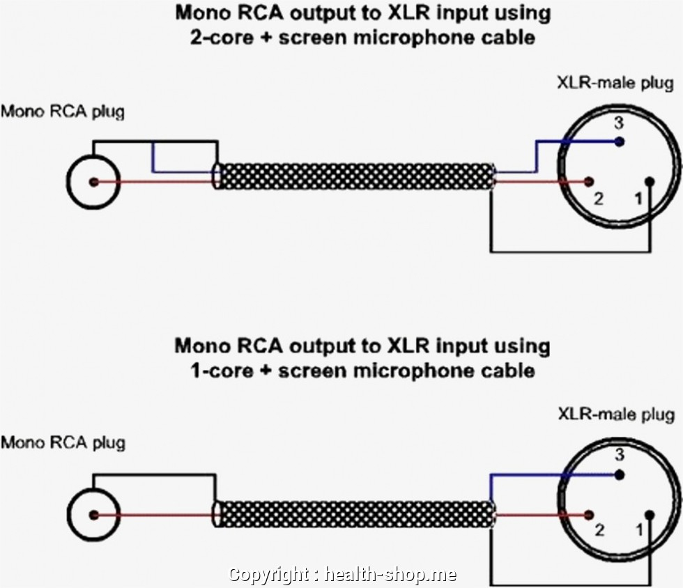
Cut the cable. Strip off the jacket. Unwind the braid (if there is one). If it's a foil shielded cable, just cut off the foil and use the bare drain wire. Cut the two insulated wires inside to the appropriate dimensions. Strip the two insulated wires to reveal 1/8th of an inch (3mm) of bare conductor on each. Tin those wire.
How To Build Your Own Xlr Cables A Stepstep Guide Studio Diy Xlr Wiring Diagram Cadician
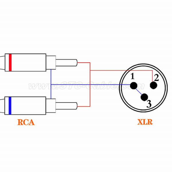
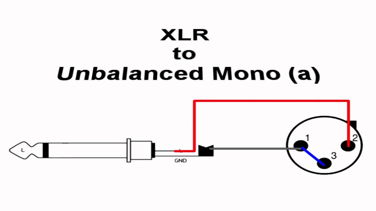
An XLR to 1/4 inch adapter wiring diagram is a diagram that shows the physical layout of the components required to wire an XLR connector to a 1/4 inch adapter. This diagram is helpful when wiring audio equipment, as it provides a visual representation of how the components must be connected. The diagram shows the physical locations of the.

Female Xlr Wiring Diagram Organicent
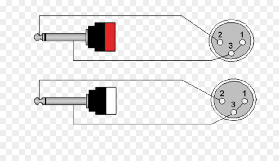
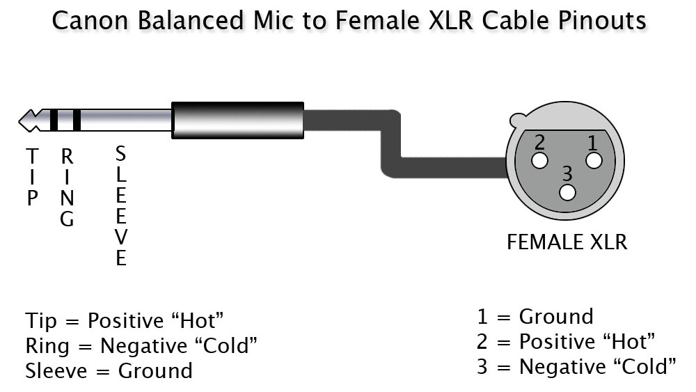
XLR is de standaard connectie voor microfoons maar wordt ook voor lijn-signalen gebruikt. De 6.3 mm (1/4 inch) TRS- of 'jack'-pluggen kent iedereen. De plug heeft drie segmenten: 'tip', 'ring' en 'sleeve', vandaar 'TRS'. De ongebalanceerde uitvoering ('asymmetrisch') heeft alleen een 'tip' en een 'sleeve' en wordt toepasselijk TS-plug genoemd.
Kabel mikrofonowy Reds Standard 3m XLRXLR
XLR cables are primarily used for professional audio, video, and stage lighting equipment. The most common XLR cable is terminated with 3-Pin XLR connectors. While there are various configurations, or "pinouts", used in wiring 3-Pin XLR cables, the AES industry standard for balanced audio XLR wiring is what is referred to as Pin 2 Hot.
Diagramme, Connecteur Xlr, Schéma De Câblage PNG Diagramme, Connecteur Xlr, Schéma De Câblage
XLR connectors are one of the most commonly used types of connection for audio and video equipment. They are used for a variety of applications such as for microphones, speakers, amplifiers, and other audio-visual devices.
Schema branchement xlr jack
December 23, 2022 by Kanishk Godiyal XLR is an electrical connector mainly used for cabling in audio and video applications. These connectors are also used in lighting control, low-voltage power supplies, etc. XLR connector was discovered by James H Cannon (the founder of Cannon Electric in Los Angeles).

DIY How To Make Your Own Audio Cables Soldering XLR and ¼" Ends AudioNewsRoom ANR
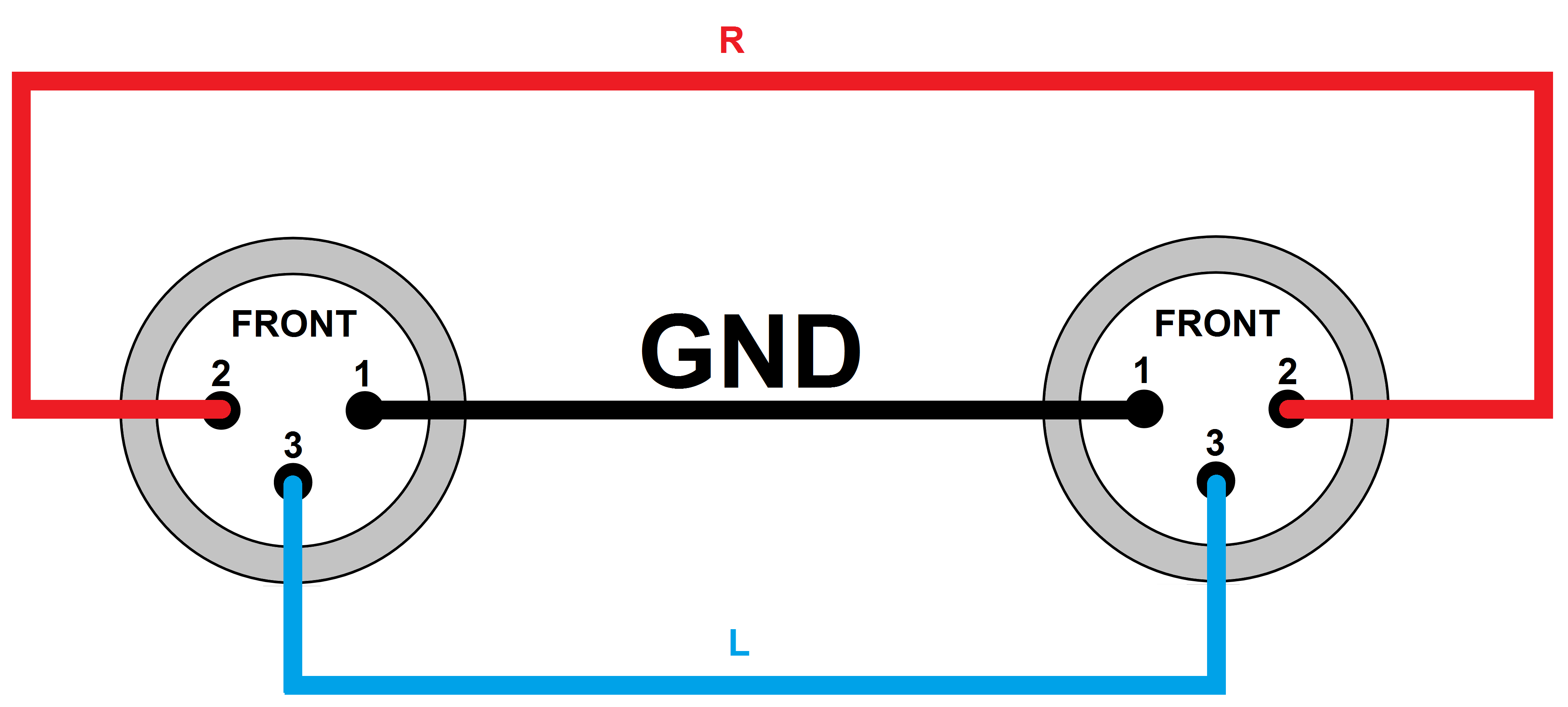
What are the electrical connections of the three pin jack (XLR) on the balanced version of a professional mic? Answer XLR pin 1 = shield; XLR pin 2 = audio +; XLR pin 3 = audio - Last Edit Date 1/29/2019
Schema Branchement Prise Xlr schémas de câblage en ligne
0:00 / 3:01 XLR connectoren solderen C&S Audiovisueel Audiovisuele installaties 103 subscribers Subscribe Subscribed 18 Share 20K views 13 years ago Deze korte tutorial laat zien hoe een XLR.
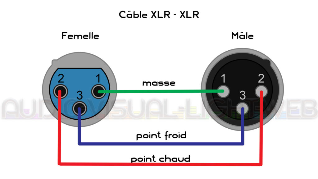
Schéma de câblage XLR 3 broches AudioVisualLightWeb
Een XLR-connector is een elektrische connector uit de professionele geluidstechniek, videotechniek en theaterbelichting. De XLR-connector werd in 1958 voor het eerst door Cannon (later als ITT Cannon onderdeel van de ITT Corporation) uitgebracht en wordt daarom ook wel de Cannon-plug genoemd. [1] Generaties
Wiring Diagram For Xlr Wiring Diagram Schemas
The use of a Wiring Diagram Xlr can simplify the process of designing and installing electrical systems. It allows a professional to quickly and easily understand the various connections that need to be made between components and wires within an electrical system. A Wiring Diagram Xlr will also provide a visual representation of the components.

Xlr Mic Cable Wiring Diagram Wiring Diagram Schemas
Design XLR connectors are available in male and female versions in both cable and chassis mounting designs, a total of four styles. This is slightly unusual as many other connector designs omit one of the styles (typically a chassis mounting male connector).

Wiring Diagram For Xlr Wiring Diagram Schemas
Mini-XLR only. One channel . 4 pin XLR female connector. Pinout status: +6 -0. According to 6 reports in our database (6 positive and 0 negative) the 4 pin XLR connector pinout should be correct. Is this pinout. correct. incorrect. 1 Related pinout(s) 5 pin XLR connector pinout; NO DIY devices
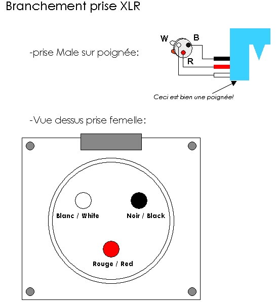
Schema branchement prise xlr
The three pin and five pin XLR pinout is a very standard connection used for audio (mic level & line level - 3 pin) and lighting control (DMX - 5-pin) applications. This article shows the XLR Pinout diagrams for both 3-pin and 5-pin connectors. You'll also discover each XLR pin's polarity. 3 Pin XLR Pinout

Xlr Wiring Diagram Lable Wiring Diagram Schemas
The female XLR connectors are designed to first connect pin 1 (the earth pin), before the other pins make contact, when a male XLR connector is inserted. With the ground connection established before the signal lines are connected, the insertion (and removal) of XLR connectors in live equipment is possible without picking up external signals (as it usually happens with, for example, RCA.